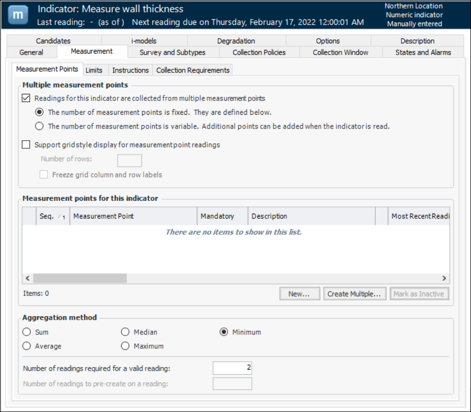
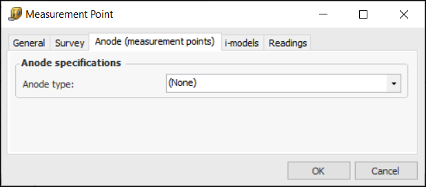
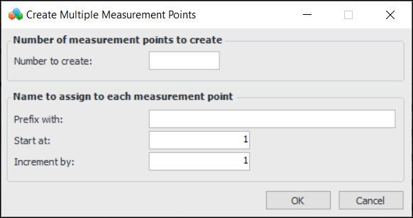
Adding Measurement Points to an Indicator

Measuring the condition of certain assets, such as piping, requires taking two or more measurements to arrive at a reliable reading for the indicator. For example, in the case of a numeric indicator that measures the wall thickness of a pipe, four to eight measurements are commonly needed at different locations around the circumference of the pipe. Descriptive indicators can also require two or more measurements, for example, an indicator that evaluates marine growth on subsea piping. The location on the asset at which measurements are taken is referred to as the “measurement location”, while the points around the asset where the individual readings are taken are called “measurement points”.
Once the values for each of the points is recorded, they are aggregated to derive a value for the indicator. For example, the lowest value might be selected or the average value. A calculation can also be used to determine the indicator state.
Measurement points are supported for manually-entered numeric and descriptive indicators. The indicator type must allow measurement points to be recorded.
Note: Measurement points are not available for indicators related to component or location assets.
Tip: You can view a list of all previous readings for the measurement point on the Measurement Point dialog, Readings tab.
This topic explains how to add measurement points to an existing indicator.

To Add Measurement Points to an Indicator

1.
2.
3.
On the Properties view, select the Measurement tab and the Measurement Points tab.
Note: The indicator type determines whether the Measurement Points tab is available. The indicator type can also provide the default selections, such as fixed or variable, aggregation method, number or readings values, and whether alarm acknowledgment is tracked for individual points.
For example:
Note: You can deactivate a defined measurement point, for example, while it is being developed. Select the point in the list and click Mark as Inactive. In the dialog that appears, you can enter an explanation for the change and click OK. Click OK to close the confirmation message that appears. The point is displayed as struck-through in the list and it will not appear in indicator readings or checksheets. To reactive a point, select it and click Mark as Active.
4.
The indicator type’s properties determine the default selection. You can change it if necessary.
You can add an individual point or multiple points at a time for either variable or fixed measurement points.
5.
To add an individual point, click New. The Measurement Point dialog appears, open to the General tab.
The Survey tab is available if a survey type is assigned to the indicator type. Select this tab to enter start and end values for the data points that are collected on the survey attached to this measurement point.
On each subtype tab, provide the appropriate information. For example, on the Anode (measurement points) tab, select the anode type:
Select the i-models tab to view i-models linked to this measurement point.
Note: For information, see Using i-models with Assets and Indicators.
Click OK. The point is added to the table. If it is mandatory, a check mark appears in the Mandatory column.
6.
To create two or more measurement points at the same time, click Create Multiple. The Create Multiple Measurement Points dialog appears.
Click OK. The points are added to the indicator.
Tip: To edit a point, select its row and press F2. The row becomes open for editing.
Press Tab until you have reached the column you want to change, edit the value, and then press Enter to finish editing the point.
7.
Sum – Readings from the measurement points are added
Average – The average of the readings from the measurement points is used
Median – Readings from the measurement points are arranged from smallest to largest and the middle value is used
Maximum – The highest reading from the measurement points is used
Minimum – The lowest reading from the measurement points is used
8.