
|
|


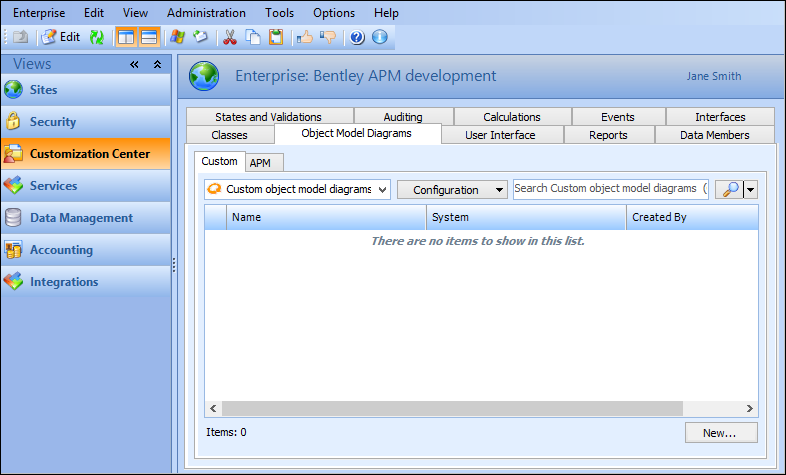
Exploring the Object Model Using an Object Model Diagram
You must be logged in with APM administrator rights in order to access the Customization Center view and object model diagrams.To Create an Object Model Diagram
You can build an object model diagram from scratch, or you can use one of the several object model diagrams provided with APM, as a basis for a diagram. Although the APM-supplied diagrams are read-only, you can right-click the diagram and select Copy to create a custom diagram based on the original. APM-supplied diagrams are found on the Object Model Diagrams, APM tab of the Customization Center.
To Create a Custom Class From Within an Object Model Diagram
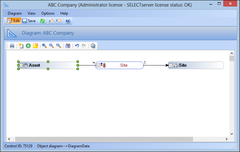
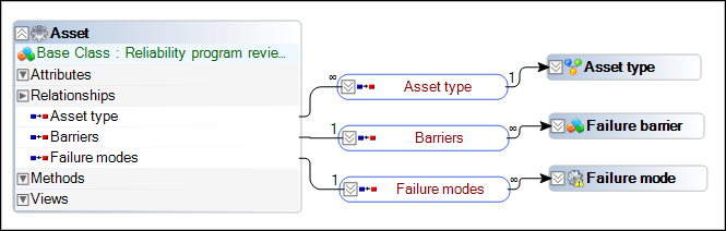
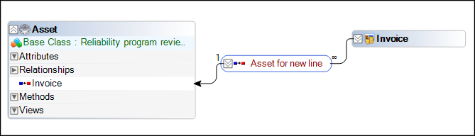
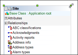
To Show and Hide Relationships
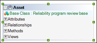
To Rearrange and Resize Objects
Tip: Multiple objects can be selected by clicking the first object, pressing and holding Shift, and then clicking the other objects.To Delete Objects
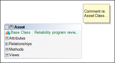
To Add a Note to an Object Model Diagram
. A yellow box predefined with the words New Note appears.
Tip: You can also right-click a blank area of the diagram and select Create Note.Tip: You can resize the comment to view all of its contents. For more information, see To Rearrange and Resize Objects.To Copy and Print an Object Model Diagram
All or parts of an object model diagram can be copied to the Windows® clipboard so that it can be pasted into other applications. A diagram may also be printed to provide a hard copy reference.
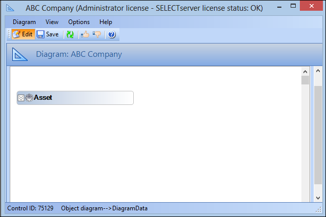
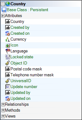
 to add a class to the diagram. The Show Class dialog appears.
 is enabled.
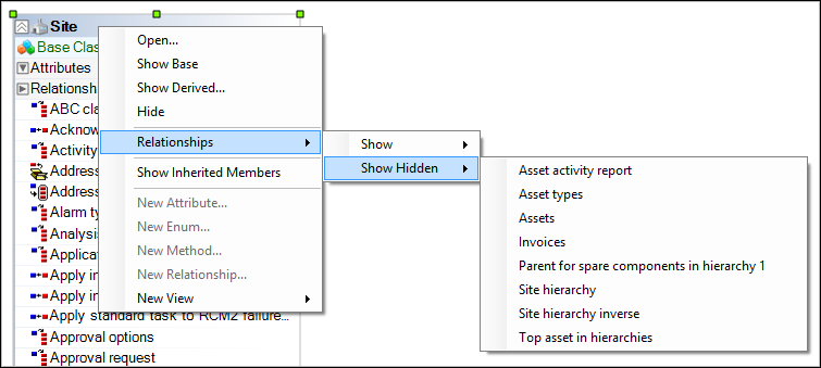
 . You can now paste the clipboard contents into another Windows
 to print the object model diagram. The Print dialog appears.